
Introduction: Why 350 kW Chargers Can Cap an EV at 50 kW
An EV can advertise a high peak charging rate and still settle near 50 kW at a public 350 kW charger. The station is usually fine. Two limits decide the outcome: the pack’s voltage and the handshake it negotiates with the dispenser. A 350 kW cabinet can only deliver what the connected car accepts, so the hardware’s headline rating says little about what a given model will actually draw. Drivers of high-voltage platforms such as the Mercedes-EQ range feel that gap most sharply.
Defining pack voltage and charger handshake
Four terms matter here:
- DC fast charging: Direct-current charging that bypasses the onboard AC charger and feeds power straight into the battery pack through the vehicle’s charging port, generally at 50 kW and above.
- Pack voltage: The total nominal voltage of the traction battery. Together with the current the cells can accept, it sets the practical ceiling for charging power.
- Charging handshake: The digital negotiation in which charger and vehicle exchange parameters over the connector’s communication pins (voltage range, maximum current, protocol) before any current flows.
- Power delivery ceiling: The lowest of three values, the station’s output, the vehicle’s acceptance rate, and the cable or connector rating, which determines the kilowatts actually delivered.
What this article covers
The rest of the article looks at the problem from both sides of the connector:
- How pack voltage architecture (400 V versus 800 V) shapes maximum charge power
- The stages of the charging handshake and where negotiation limits take effect
- Why a 50 kW ceiling can appear even on 350 kW chargers
- Practical steps owners and engineers can take to predict real-world charging speed
EV Pack Voltage Fundamentals: Series Cells, Architecture, and the Charging Ceiling
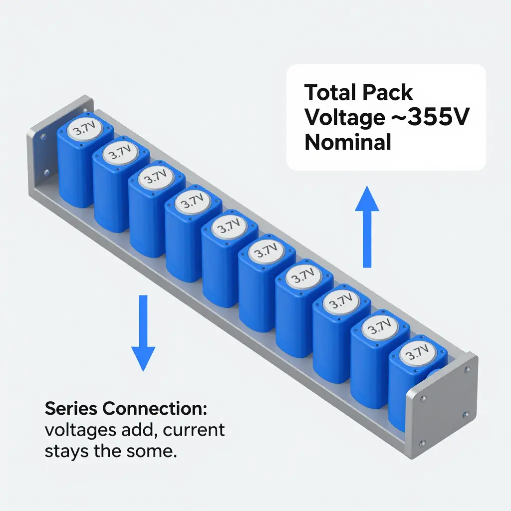
A traction battery is a long string of cells wired in series, and that one arrangement explains most of the difference between a fast charge and a slow one. In a series string the cell voltages add up while the current stays the same, so more cells in series means more voltage at the same amperage.
How series cells create EV pack voltage
A single lithium-ion cell rests near 3.6-3.8 volts. Stack 96 in series and the pack idles around 355 volts, the basis of what the industry calls a “400V” architecture. Double the count to roughly 192 and nominal voltage lands near 710 volts, climbing to about 800 volts at full charge. Series cell count is the biggest lever an engineer has over pack voltage.
Why 400V and 800V dominate
400V packs won the first decade of EVs because they matched the 400-500V silicon already used in industrial drives, keeping inverters, cables, and safety gear affordable. When fast charging became a selling point, manufacturers doubled the series cell count to reach roughly 800V, letting the same copper busbars carry twice the power.
Three voltages worth knowing
- Nominal voltage – the pack’s average resting voltage, roughly the series cell count multiplied by each cell’s mid-charge voltage (about 3.7V). It is the headline number, like “400V.”
- Max charge voltage – the ceiling a charger may reach, typically around 4.2V per cell stacked in series (roughly 403V for a 96-cell string). Beyond it, cells degrade or become unsafe.
- Usable pack voltage – the window between the low-voltage cutoff and the max charge voltage that the battery management system actually lets you access.
Voltage sag and internal resistance
Every cell has internal resistance, and every amp you draw pushes voltage down across it. That momentary dip is voltage sag: a pack resting at 400 volts might read closer to 360 volts under hard acceleration or heavy DC charging. Higher current and higher internal resistance make the sag deeper.
Why pack voltage sets the charging ceiling
A DC charger cannot push current unless its voltage exceeds the pack’s present voltage, and it must stop at the max charge voltage. Because power equals voltage times current (P = V x I), a higher-voltage pack accepts more power at the same current.
That is why an 800V car can absorb 350 kW while a 400V car on the same cable tops out near half that: the pack voltage, not the charger, is the real ceiling. Managing these limits in real time falls to the pack’s software, much like the systems behind Mercedes EQS battery and charging software.
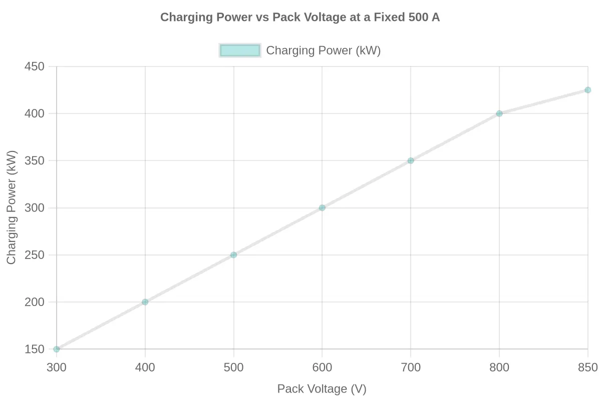
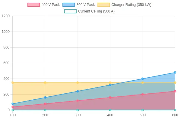
Hold current at 500 A and the power curve rises straight with voltage, doubling the instant the pack doubles its series cell count.
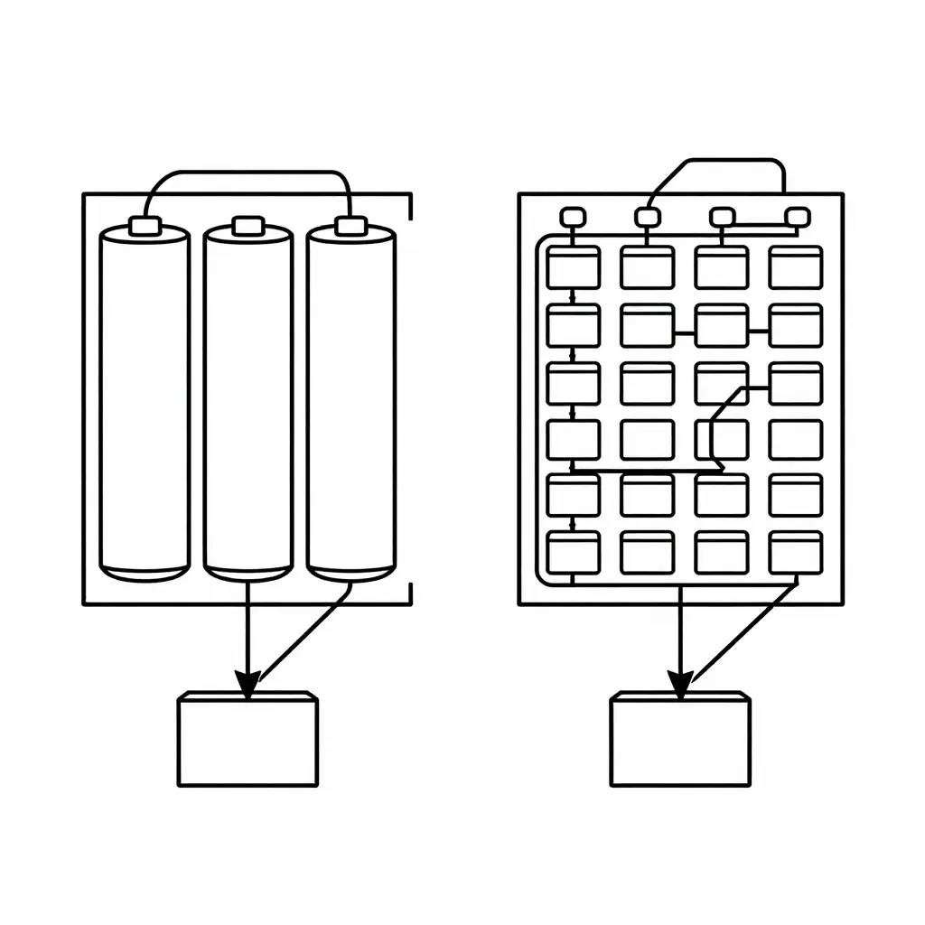
Inside the Charger Handshake: How Your EV and a DC Fast Charger Negotiate Power
Plug an EV into a DC fast charger and neither side simply dumps current into the pack. A structured charger handshake plays out in stages, mixing physical safety checks with digital negotiation. The sequence is why a car rated at 150 kW can pull only 50 kW from a 350 kW dispenser.
Stage 1: Physical Connection and Safety Checks
The moment the connector seats, the charger verifies the Control Pilot and Proximity Pilot circuits. It confirms the latch is engaged, then runs insulation resistance and ground-fault checks. Only after these pass does the charger close its contactors and expose voltage to the vehicle.
Stage 2: Digital Communication (PLC over CCS)
With hardware verified, the two sides begin high-level communication. On CCS networks this runs as Power Line Communication (PLC) using the ISO 15118 stack. The vehicle and charger exchange messages that carry critical parameters:
| Data Exchanged | Why It Matters |
|---|---|
| State of charge (SoC) | Sets the target and taper curve |
| Pack voltage limits | Defines the window the charger must supply |
| Cell temperature | Protects cells from thermal stress |
| Maximum allowable current | Caps what the BMS will accept |
Stage 3: Power Offer and Setpoint Agreement
The charger then presents a power offer constrained by its own output and the cable rating. The Battery Management System (BMS) replies with a current and voltage setpoint it can safely absorb. Both must land inside a shared envelope.
If the vehicle’s supported voltage range does not overlap the charger’s output window, the session drops into a lower-power mode such as 50 kW. A 400 V pack cannot fully exploit a 350 kW, 800 V-optimized dispenser, so the negotiation settles on a reduced setpoint rather than the headline rating.
Where Diagnostics Come In
Engineers trace these exchanges with diagnostic and software tools, monitoring CAN and PLC logs to see whether the cap came from thermal derating, SoC, or a genuine voltage mismatch. Vehicle-side logic that governs these parameters is configured through model-specific charging software, much like the configuration described for the Mercedes EQS charging software setup. Reading the handshake turns a confusing slow session into an explainable one.
One rule of electricity anchors everything that follows: power (measured in kilowatts) equals voltage multiplied by current (P = V × I). If either the amps or the volts are constrained, the product cannot grow.
| Architecture | Typical Pack Voltage Range | Charger Max Output Current | Theoretical Max Power (V x A) | Real-World Peak Power Observed |
|---|---|---|---|---|
| 400V class | 350-450V | Up to 500A | ~175-225 kW | 120-180 kW |
| 500V class | 450-550V | Up to 500A | ~225-275 kW | 180-250 kW |
| 800V class | 700-880V | Up to 500A | ~350-440 kW | 270-350 kW |
| 1000V-ready (newest) | 800-920V | Up to 500A | ~400-460 kW | 320-400 kW |
| 350 kW charger fixed ceiling | 350 kW / 500A = 700V required | Locked at 500A max | 350 kW only above ~700V | 50-200 kW on lower-voltage packs |
Taken together, the table shows that the charger’s current limit, not its nameplate kilowatts, is usually the binding constraint. A 350 kW charger capped at 500A reaches its advertised 350 kW only when the pack sits at roughly 700V or higher. Put that same 500A ceiling on a 400V pack and the math falls to around 200 kW theoretical, often far less in practice once thermal tapering and the handshake take their bite. That is why 350 kW chargers frequently deliver only a fraction of their headline number to lower-voltage vehicles, and why owners of cars running a 400V architecture may see a peak that barely clears 50-150 kW. Raising pack voltage lets the same current limit produce more power, which is why high-voltage platforms such as Mercedes EQS software-managed models get closer to the charger’s rating.
The Power Equation Behind DC Fast Charging
Every fast-charging session reduces to one electrical relationship: Power (kW) = Voltage (V) x Current (A) / 1,000. Power is a product, so it can only grow as large as its two factors allow. That is why the “350 kW” printed on a charger’s screen is a promise the cable frequently cannot keep.
The Current Ceiling Is Fixed by the Hardware
Public DC cables and connectors are rated for a maximum continuous current, typically 350-500 A depending on conductor gauge, liquid cooling, and connector standard. That ceiling belongs to the cable and connector, not to the charger’s power electronics. Resistive heating rises with the square of current (P = I^2R), so conductors are either actively cooled or kept deliberately current-limited. Because the ceiling is fixed in amps, the same cable produces very different power at different pack voltages. A 400 V pack at 500 A yields 400 x 500 = 200 kW; an 800 V pack at the same 500 A yields 800 x 500 = 400 kW. The 400 V car reaches only about 57% of the 350 kW rating, while the 800 V car saturates it.
Cable, Connector, and Thermal Derating
Two physical bottlenecks stack on top of each other. First, the charger may cap current well below what the pack could accept. Second, thermal derating reduces that cap further as connectors and cable conductors warm up, because the hotter the conductor, the lower the sustainable amperage. This is why the delivered-power line on a charging power curve tapers after its peak instead of staying flat. The pack, cables, connector, and charger electronics all negotiate through the handshake, and the lowest common limit wins. Even the vehicle’s negotiation layer, like the logic found across Mercedes-EQ charging software, decides how much of the available current the pack will actually accept.
Charger-Rated Power vs. Delivered Power
Rated power is the nameplate maximum the station advertises; delivered power is what actually reaches the battery after every limit is applied. Here is the arithmetic for a real-world case:
- Read the charger’s nameplate rating: 350 kW.
- Note the cable’s continuous current ceiling: 500 A.
- Read the pack’s voltage under load: 400 V.
- Multiply volts by amps: 400 V x 500 A = 200,000 W = 200 kW.
- Compare with the nameplate: 200 kW / 350 kW is about 57%.
- Repeat for an 800 V pack: 800 V x 500 A = 400 kW, clipped by the charger to 350 kW.
On a current-limited charger, voltage, not the kW badge, decides how much power the car can pull. Owners see the difference on the screen; engineers see P = V x I with a hard ceiling on I.
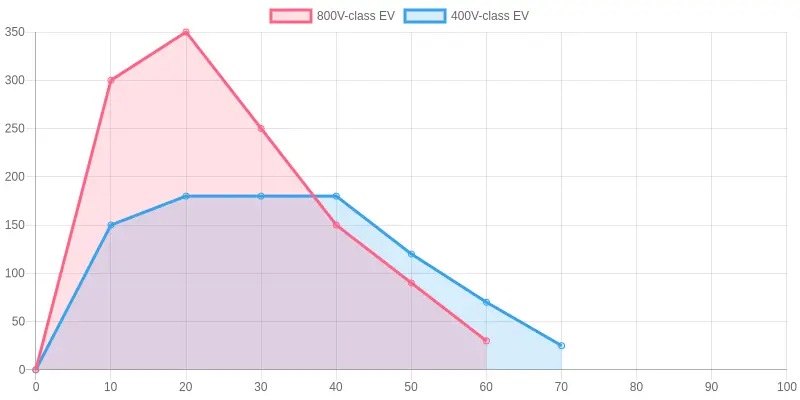
The 400V-class EV plateaus at a visibly lower power level than the 800V-class EV on the very same 350 kW charger. The 800V series climbs quickly to near the charger’s ceiling, while the 400V series flattens out much earlier, a direct picture of the current-limited cap imposed by its lower pack voltage.
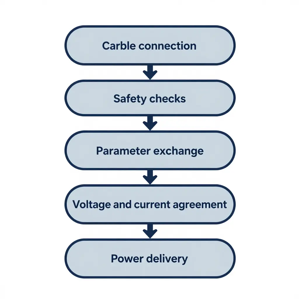
The handshake unfolds as a strict sequence: cable connection, safety checks, parameter exchange, voltage and current agreement, then power delivery. Miss or stall any step and the charger throttles you down.
Real-World Implications and Diagnostic Context
A “350 kW” label on a charging station describes the charger’s ceiling, not what your car will actually pull. That figure assumes a battery pack, onboard charger, and cooling system capable of absorbing the full rate. When a vehicle advertises “ultra-fast charging” yet delivers a modest 50 kW, the bottleneck usually sits on the vehicle side: pack voltage, state of charge, temperature, and the negotiation handshake itself.
Labels vs. Delivered Power
Owners should treat charger ratings as capacity and delivered power as a negotiated outcome. The station may offer 350 kW, but the car’s battery management system (BMS) requests only what the pack can safely accept at that instant. A 400 V architecture cannot use the full current an 800 V-tuned cable and station can supply, so the session settles well below the label.
| Concept | What it describes | Typical example |
|---|---|---|
| Charger label | Maximum station output | 350 kW |
| Negotiated request | What the car asks for | 120 kW |
| Delivered power | Actual flow reached | 50 kW |
How Software and Firmware Shape Negotiation
The handshake is governed by firmware, not hardware alone. The vehicle’s software defines the charging curve, the acceptable voltage window, and the timing of the current request. A conservative curve, a thermal protection threshold, or an outdated communication stack can all cap the session regardless of how capable the charger is. That is why two identical cars can behave differently at the same plug.
Software updates and diagnostics also influence reported limits. A firmware revision can raise or lower the advertised peak, adjust how the BMS announces itself, or fix a protocol quirk that previously forced a fallback rate. Knowing how manufacturer software changes may influence charging-related behavior helps owners and engineers separate a genuine hardware ceiling from a calibration choice. Logging the actual handshake messages with proper diagnostic tooling turns guesswork into evidence, revealing whether the car or the station is the limiting party. The number on the pedestal is a promise; the number on your dashboard is the result of a conversation your vehicle’s software controls.
Seeing the Gap: Real-World Peak Charging Power by Class
Typical real-world peak charging power on the same 350 kW charger, by vehicle class:
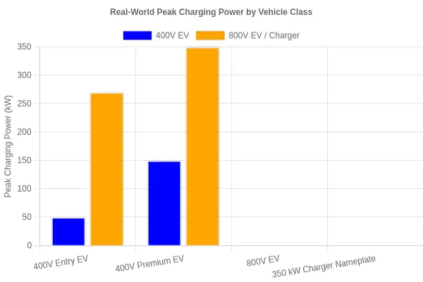
| Vehicle / Hardware Class | Nominal Pack Voltage | Typical Real-World Peak |
|---|---|---|
| 400V entry EV | 400V | 50 kW |
| 400V premium EV | 400V | 150 kW |
| 800V EV | 800V | 270 kW |
| 350 kW charger (nameplate) | – | 350 kW |
The two short bars on the left are not a charger failure. They are the current-limited ceiling a 400V architecture hits when the cable can only push a fixed amperage. An entry-level 400V car capped near 50 kW is following the power equation: P = V × I, and if the volts stay low, the watts stay low too. Step up to an 800V pack and the same amperage buys a far taller bar. The charger’s 350 kW nameplate is a ceiling almost nobody touches; the real ceiling is set by how much voltage your pack can present to the handshake. To see how these control modules and their firmware programs negotiate that voltage, it helps to understand the star diagnostic platform that talks to Mercedes EV electronics during service.
Frequently Asked Questions
Why does my EV stop at around 50 kW on a 350 kW charger?
A charger cannot force power into a car; it can only deliver what the vehicle’s battery management system requests. The “350 kW” label describes the station’s maximum capacity, not a guaranteed rate for every vehicle. If your car settles near 50 kW, its request is likely capped by pack voltage, current limits, temperature, or state of charge. The gap between a high-voltage charger and the car’s actual acceptance rate explains most of these cases.
Does a higher-voltage pack always charge faster?
No. A higher nominal pack voltage raises the theoretical ceiling because power equals voltage multiplied by current. Real charging speed also depends on peak current, cell chemistry, thermal management, and how aggressively the manufacturer tunes the curve. A well-cooled 400V pack can sometimes outcharge a modestly engineered 800V pack across a full session.
What is the charger handshake and why does it matter?
The handshake is the digital negotiation between the car and the charger before energy flows, typically handled through the CCS protocol and ISO 15118. During this exchange, the vehicle and station agree on voltage, current, and safety parameters. The relationship between pack voltage and charger handshake is central to performance: if the two sides cannot match limits, the session runs at the lower value. A failed or throttled handshake is a frequent reason for unexpectedly slow charging.
Can software updates change my charging speed?
Yes. Battery management firmware defines the charging curve, including how much power the pack accepts at each state of charge and temperature. Manufacturers occasionally revise these curves to improve longevity, add thermal safeguards, or unlock faster sessions. Owners of electric models can check Mercedes EQS software updates to see how such revisions are delivered.
Why does charging slow down at a high state of charge?
As the battery fills, the cells become harder to charge without stress, so the BMS tapers current to protect them. Pushing full power into a nearly full pack can cause lithium plating and excess heat, which shorten battery life. This tapering is deliberate engineering, not a fault, and it is why the final 20 percent usually takes the longest.
Is a 350 kW charger useless for a 400V car?
No. A 400V car will still work on a 350 kW station; it simply cannot use the station’s full output. Many 400V vehicles top out well below the charger’s rating because their architecture limits the current they can accept. The station adapts to the car’s request, so the session is slower than the headline figure but still functional.
Conclusion: The Lower Limit Always Wins
On any DC fast charger, your EV can only draw as much power as the smaller of two numbers allows: what the pack’s voltage architecture can physically support, and the current ceiling the charger is willing to deliver. The handshake is the moment those two limits meet and get agreed upon.
The pack-voltage classes covered above run from 400V workhorses to 800V platforms and the transitional ranges between them, and each one shapes the real-world charging curve. Because P = V × I, both voltage and current have to rise for speed to climb. Legacy pack designs, conservative BMS logic, thermal management, and charger-side current limits all throttle sessions in practice. Doubling voltage halves the current needed for the same power, which cuts heat and gets an 800V car closer to a 350 kW charger’s full output.
Voltage architectures and software coordination will keep evolving together. Higher-voltage platforms and more flexible handshakes, like the ongoing refinement captured in modern Mercedes EQS software, will continue to narrow the gap between what chargers advertise and what cars actually accept.